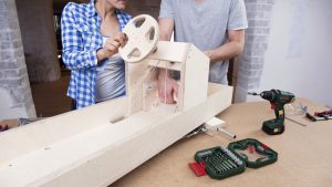
Bosch: Go-kart for little race-drivers
Posted by Tanya Schutte in Project Plans
What it lacks in speed, it more than makes up for in fun: the go-kart will excite little race-drivers.
Introduction:
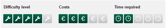
It’s “only” a go-kart, but it’s equipped with some technical refinements. Beginners should schedule two days for this project, while experts will manage it in one. The costs are £150 – £200.
The following construction guide is designed for 18 mm, 24 mm and 9 mm thick birch multiplex panels. Have the required panels cut to size at a DIY store or by your carpenter. If you use other materials or material with a different thickness, adapt the parts list accordingly. Control cables also give the go-kart steering and braking. Of course, the front axle has to be movable for this to work. And the brake rods have to be movable, too. You will find the detailed material list and the construction drawing under Downloads.
Required power tools:
Other accessories:
- 10-mm drill bit
- 30-mm drill bit
- Spanner
- Countersink
- Small slotted screwdriver
- Long nose pliers (“telephone pliers”)
- String and pencil or compass up to 200 mm diameter
- Sanding paper, grit of 120–240
- Pencil, metre stick, sharpener, rubber
- Work surface
- Sheeting or old newspapers
- Trestles if available
Downloads for this project:
PDF download
Plan (PDF – 3.5 MB)
STEP 1: Assembling the base tray from the base plate and frame strips.
- First prepare the base plate. When doing so, observe the dimensions specified in the construction drawing. Use the pencil to mark the cutouts for the control cables and then saw them out with the jigsaw. Before sawing, pre-drill the four corners with the 10-mm drill bit. This will make it easier to manoeuvre the saw blade around the corners.
- Now mark the holes where the brake rods and the steering axle will later be fitted. The two holes for the brake rods each need a recess for the screw heads on what will later be the inside of the base plate. First use the 30-mm Forstner drill bit to drill 5 mm deep at the corresponding positions in the plate. Then drill two 8-mm-diameter holes in the same position for the brake rods and a 10-mm hole at the front centre for the steering axle.
- Once you have marked the position of the rear axle on the bottom of the base plate, mount the longitudinal and horizontal frames with the base plate to form a tray. To do so, pre-drill the base plate with 4 mm diameter and fix the base tray with 18 wood flat head screws (3.5 x 50 mm).
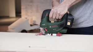
Application Tip – How to saw curves with ease.
You’re building a go-kart and have to saw the steering wheel into shape. Or you want to saw cutouts in a wooden box to make it easier to carry. It is best to use a jigsaw for jobs like these where you have to saw a curve.
Procedure:
- Simply follow this advice to make sure that you saw curves correctly:
- Insert a curve-cutting blade into your jigsaw. When selecting the saw blade, also pay attention to the condition of the workpiece material – for example, is it hard wood or plywood, a board or a panel?
- Precisely mark the cutting line on your workpiece with a pencil, compass and ruler. If you are sawing a cutout, drill a hole touching the marked line and big enough to insert and turn the blade of your jigsaw in.
- To drill curves with a very small radius, it is best to use a drill bit with the corresponding diameter. Now use the jigsaw to saw up to the edge of the hole and from there along the previously marked line.
- Be sure to guide the saw correctly. The more your hand is above the saw blade, the more precisely and easily you will be able to saw curves and straight lines.
STEP 2: Bottom of the tray.
- Now screw the strip for the steering stop as specified in the construction drawing with 3.5-x-30-mm screws on the bottom of the base plate.
- To ensure that the steering axle glides better, you also fit two acrylic glass plates to it as a glide layer. When doing so, make sure that the heads of the flat head screws (3.5 x 35 mm) completely disappear into the plates.
- Pre-drill the two fixing strips using the 6-mm drill bit and mount a ring nut with a carriage bolt (6 x 50 mm) on each strip. The control cables for the steering and the brakes will later be fed through the ring nuts. Now mount the fixing strips with wood screws (3.5 x 30 mm) on the bottom of the base plate.
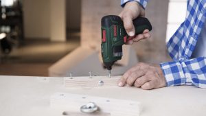
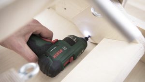
TIP FOR SCREWING TOGETHER TWO WOODEN PARTS
In the piece where you want to insert the screws first, always pre-drill a hole that is 0.5 to 1 mm larger than the screw diameter; the hole should be countersunk deep enough for the screw head to completely disappear into it. In the piece that you are going to drill second, pre-drill a hole that is always 1 mm smaller than the screw diameter. This ensures that the screw thread will still grip well.
Procedure:
How to ensure nice, strong screw joints:
- Use a wood drill bit with a centring tip. You can use a twist drill bit for normal holes with small to medium diameter. An auger bit is recommended for drilling deep holes with diameter of 8–10 mm or more. The Forstner drill bit is suitable for drilling shallow holes of up to 30 mm diameter. The holesaw is ideal for drilling through-holes with 30 mm diameter or more.
- Always use wood screws. They have a high-incline thread and a pronounced tip. The shank is cylindrical or conical.
- (Cordless) screwdrivers and (cordless) drill/drivers are ideal for screwdriving. If you only need to drive screws occasionally, you can also use a drill.
- Make sure that the bit you use in your tool fits the screw perfectly. Otherwise it might slip out of the screw during screwdriving. “Torx” screws offer the best grip, “cross head” screws (technical term: Pozidriv or Philips) are generally better suited than slotted screws.
- You will achieve the best result by drilling along the grain of the wood. Set the right speed. If the speed is too low, the resulting hole will be untidy. If the speed is too high, there is a risk of the workpiece overheating and burn marks occurring. Place the drill bit cleanly against the workpiece.
- Fix the workpiece using clamps to prevent it from slipping during drilling. Place a scrap panel underneath the workpiece, so that you can drill into the scrap panel without damaging your worktop. This also prevents fibres from being torn out when you drill through the workpiece.
- To connect two pieces of wood with screws, always pre-drill a hole that is 0.5 to 1 mm larger than the screw diameter in the piece where you want to insert the screws first. In contrast, you should always pre-drill a hole that is 1 mm smaller in the piece you are screwing into. This ensures that the thread will grip well.
- If you are using flat head screws, countersink the drilled hole deep enough for the head of the screw to disappear into it completely.
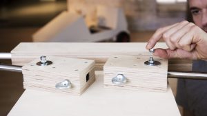
STEP 3: Making the wheel axles and brake rods.
- The wheel axles and the steering rods each consist of four wooden strips surrounding a metal rod: a support strip, two spacer strips and a fixing strip.
- To enable the go-kart to be steered, the front axle is, of course, movable. It will later be controlled using a control cable. The two brake rods are also fitted as movable parts. The rear wheel axle is, on the other hand, rigid.
- Drill two 6-mm-diameter holes, each 35 mm in from the edge, into the front axle’s spacer strip. Fit the two ring nuts for the control cable in these holes, each with a carriage bolt (6 x 50 mm).
- To enable you to later mount the front axle as a movable part on the base plate, drill a 10-mm-diameter hole for the carriage bolt (10 x 60 mm) in the middle of the support strip. The head of the carriage bolt must disappear into it completely. For this reason, use the 30-mm Forstner drill bit to drill an approx. 5 mm deep countersink.
- The front and rear axles are assembled in the same way: line up the metal rod in the middle of the support strip and position the spacer strips on the right and left of it without leaving any space. Then put the fixing strip on top and screw together the strips on both sides from above (don’t forget to pre-drill). To make sure that the metal rod cannot slip, drill a 4.5-mm-diameter hole through the middle of the wood into the metal rod. Then insert a screw (4 x 25 mm) to lock it.
- The two brake rods are built according to the same principle as the wheel axles. Since the brake rods are movable like the steering axle, you again fit ring nuts for the control cables here and drill the holes for the subsequent movable attachment to the base plate with the carriage bolt (8 x 90 mm). Don’t forget to fix the two metal rods with a screw, so that they do not slip out of the wooden blocks. To make sure that the brakes work really well, a piece of rubber hose is put on each metal end.
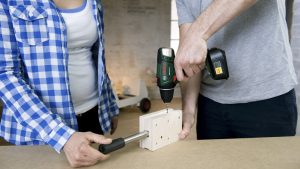
Application Tip – Small detail, big performance.
Furniture often looks more appealing when the corners and edges are chamfered, i.e. sanded at a 45-degree angle. This task is perfect for the handy and versatile multi-sander or the specialists for hard-to-reach areas: delta sanders and compact belt sanders.
Procedure:
How to sand corners, edges and angles effortlessly:
- To chamfer wood edges, choose sanding paper with a grit of 120 to 180.
- Switch on the sander, apply it at a 45-degree angle and slowly pull it over the edge of the workpiece.
- Delta sanders and compact belt sanders are ideal for sanding in hard-to reach angles. Using the right attachment, you can also use the multi-sander for this task.
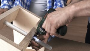
STEP 4: Mounting the wheel axles and brake rods on the base tray.
- The rear axle is fitted to the base plate by simply screwing it from the inside of the base tray with 4 screws (5 x 60 mm).
- To fit the wheel axle and the brake rods, place the base tray on the worktop with the base facing up.
- Now the steering axle is connected to the base plate as a movable part by a carriage bolt. Insert the bolt through the steering axle, put the two washers on and feed the bolt through the pre-drilled hole in the base plate. Put another washer on the inside of the base plate and fix the bolt with two lock nuts.
- Similar to the steering axle, the two brake rods are fitted to the bottom as movable parts each with a carriage bolt (8 x 90 mm), complete with a washer and two lock nuts. The heads of the carriage bolts are countersunk in the pre-drilled recesses in the base plate. This will enable you to later place the seat there without any problems.
Application Tip – How to sand smoothly.
Sanding wood surfaces is one of the most common applications performed by DIYers. For example, to remove surface blemishes and paint residues or to prepare the wood for further surface treatment.
Procedure:
Here you can find out how to sand correctly, especially on curved surfaces.
- Using the right tool also determines the work result. The random orbit sander is especially suitable for curved surfaces due to its round sanding plate.
- Guide the sander over the wood surface slowly and without applying pressure.
- When sanding natural wood, you should always sand the visible surfaces with the grain. This will achieve the best result.
- First sand with coarser grit (150, 180), then with finer grit (up to 240) sanding paper. Replace used sanding paper as soon as it is worn out.
- To be safe, wear protective glasses.
STEP 5: Sawing the steering wheel into shape.
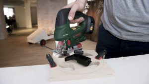
- Mark the outline of the steering wheel on the panel with the compass: first the outer circle with 200 mm diameter, then the inner one with 170 mm. Then mark the triangles for the cutouts.
- To make it easier for you to saw these out with the jigsaw, drill 10-mm-diameter holes beforehand at the inner corners. To do so, use G-clamps to fix the panel on a scrap panel that you can drill into. Also pre-drill four holes (4 mm diameter) through which you will later fit the steering wheel to its fixing.
- To saw the cutouts, it is best to use a thin curve-cutting saw blade. To then saw the circular outline of the steering wheel, set the radius on the guide rail and fix it as a compass with a pin in the centre.
- Finally, chamfer all edges and sand them smooth. Alternatively, you can use a router to cleanly rout out the steering wheel and round off the edges with a 5-mm radius bit.
STEP 6: Making the steering unit and fitting the steering wheel.
- Mark the two side sections of the steering unit as specified in the construction drawing and saw them out with the jigsaw. Drill an off-centre 6-mm-diameter hole in each of the two side sections to attach the ring nut with the carriage bolt (6 x 40 mm), and then fit them. The steering cable will later be fed through the ring nuts.
- In each of the horizontal strips of the steering unit, you drill a 20-mm-large hole in the middle for the steering axle. Mount the side sections and the horizontal strips with screws (3.5 x 50 mm).
- You also drill a 20-mm-diameter hole in the middle of the steering wheel fixing. You drill a 4-mm-diameter hole on one side for the lock. Now put the fixing on the steering rod, pre-drill with the 3-mm drill bit and lock the steering wheel fixing with a screw (3 x 60 mm). Then screw the steering wheel onto the fixing with four screws (3.5 x 40 mm).
- Now the steering rod is inserted into the corresponding holes of the steering unit and aligned with shaft collars and set screws. To make sure that the steering cable does not slip later on, slit open a piece of rubber hose and put it around the steering rod.
STEP 7: Building the brake pedal.
- Now you assemble the brake pedal. Mark the outline for the side sections and cut them with the jigsaw. Then drill a hole in each side of the pedal for the carriage bolt (6 x 40 mm) and the ring nut that the control cable for the brakes will later be attached to.
- You drill a 6-mm-diameter hole in each of the side sections for when the pedal is later fitted. Now mount the brake pedal with screws (3.5 x 40 mm) and fit the two ring nuts.
STEP 8: Cutting the body components to size.
- To determine the exact position of the steering unit, saw the side sections into shape beforehand. Transfer the outline onto the panels and cut them out with the jigsaw or hand-held circular saw. You should pre-drill the inner radius beforehand with 10 mm each to make it easier to turn the saw blade.
- Whilst doing this, you can also cut the other parts of the bodywork to size. Do the bonnet in exactly the same way as the side sections.
- The second tail is a little more complicated. As it is slanted, you will have to make mitre cuts at a 25-degree angle on the top and bottom with the jigsaw or circular saw.
STEP 9: Installing the steering unit and brake pedals.
- Now connect the steering unit to the frame in the right position. Use the two connecting pieces to do this and mount them each with four screws (3.5 x 30 mm) on the frame and on the steering unit.
- Then screw the brake pedal to the connecting pieces (with two 5-x-50-mm screws). Make sure that the pedal remains movable.
STEP 10: Fitting the control cables for the steering and braking.

- Fix the control cable for the steering to the ring nut at the right-hand front wheel with a simplex clamp. Pull the cable through the ring nut on the right-hand base plate and through the cutout in the base plate up via the ring nut on the right of the steering unit to the steering axle.
- Here you wrap the cable around the rubber casing three times and feed it further via the ring nut on the left of the steering unit down to the left-hand base plate where you feed it through the ring nut again towards the left-hand front wheel. Fix the turnbuckle under the base plate with another simplex clamp. Connect the other end of the turnbuckle with a carabiner to the ring nut on the left-hand side of the front axle. Now you can tighten the cable with the turnbuckle.
- For the brake, a control cable runs from each side of the pedal through the opening in the base and the ring nut to the brake rod. Fix the cables to the ring nuts on the brake pedal with simplex clamps. Again add a turnbuckle at the back and fix it with a carabiner to the ring nut on the brake rod.
- To ensure that the brake releases, screw on a return spring from below for each brake between the brake rods and the rear axle with spacer rings and washers.
- When everything is connected, rotate the turnbuckle to apply sufficient tension to the brake cable.
STEP 11: Fitting the body components.
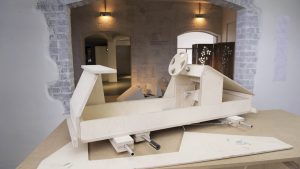
Now the bodywork of the go-kart needs to be fitted. Firstly, screw on the radiator and the first tail. Then fit the side sections. Now you can mount the bonnet on the side sections and the radiator. Then fit the second tail between the side sections (each with 3.5-x-30-mm screws). Finally, mount the spoiler and the bumpers with screws (3.5 x 40 mm).
STEP 12: Mounting the wheels and installing the seat.

- Before you can drive it, the go-kart needs a seat and wheels. Each wheel is held in position by two shaft collars. Simply slide the first shaft collar onto the axle, then the wheel and then the second shaft collar. The shaft collars are locked with set screws.
- The seat consists of the seat frame, the backrest and the seat panel. Mark the outline and saw the components into shape with the jigsaw. Pre-drill holes through the seat frame (5 mm diameter), so that you can later mount the seat on the go-kart, and screw the backrest to the seat frame. Then you can place the seat in the go-kart. Once it is in the right position, tighten the screws. Finally, fit the seat panel.
- To be safe, now check all connections again. Then your go-kart is ready to go.
STEP 13: Done.

- It’s great if you had fun doing the project. But now comes the real fun. It’s time to hit the track with this sporty car!
Product recommendations:
Legal note:
Bosch does not accept any responsibility for the instructions stored here. Bosch would also like to point out that you follow these instructions at your own risk. For your own safety, please take all the necessary precautions.
MAKE YOUR HOUSE A HOME.
Home made by you.
Design, build and style your own home – just the way you want it. We can help you with inspiring projects, helpful tutorials and useful tips from our craftsmen and gardeners – until your house really does feel like home. Get your creative juices flowing and make it happen!
![]()
Comments
Add comment